FREESTANDING CHIMNEYS
From the project to the final assembly
ANALYSIS OF A PROJECT WITH A FREESTANDING CHIMNEY SOLUTION
We define the main steps to follow to design a system with a freestanding chimney solution:
The initial data are essential to begin the development of the project:
- PLACE OF INSTALLATION. The exact location of the installation site is necessary to determine the wind speed and the seismic zone.
- HEIGHT (m). The height is used to define the atmospheric pressure, and is used to calculate the section of the flue gas duct.
- MAXIMUM AND MINIMUM ZONE TEMPERATURE (ºC). The annual averages of the minimum and maximum zone temperatures are used respectively for the calculation of the flue gas duct section and for the evaluation of condensate formation.
- NUMBER AND TYPE OF GENERATORS (boiler, steam generator, power unit, cogenerator, etc.), fuel, power, (kW, kcal / h)
– Efficiency (%)
– Smoke mass flow (kg / h) or volume flow (m3/h, Nm3/h)
– Nominal / minimum flue gas temperature (ºC)
– Minimum draft or maximum available overpressure (Pa, mmca)
– Diameter (mm) or flue outlet flange.
The information of the generator is used to define the material and the section of the flue and check its height with the environmental limits imposed by local regulations.
The technical data required for the execution of the study will be used in accordance with the EN 1991-1-4: 2007 and EN 13384-1 STANDARDS
FREESTANDING CHIMNEYS
Definition of the diameter
Defined all the project data, we proceed with the initial study, in the following evaluations:
Definition of the diameter
The calculation of the diameter of the freestanding chimneys is done following the specifications of the EN 13084-1 standard. This standard establishes that for heights of less than 20 m the calculation method envisaged by the EN 13384-1 standard can be used. For heights equal to or greater than 20 m, the calculation of the diameter must be performed according to the terms established in annex A of the EN 13084-1 standard.
This annex introduces a further verification for the requirements contained in EN 13384-1, which are described below:
- The speed of the fumes at the exit of the chimney must be greater than a minimum value which is a function of its diameter.
FREESTANDING CHIMNEYS
Configurations
MULTIPLE FREESTANDING
The multiple chimneys are built with a resistant external self-supporting pipe not in contact with the fumes, which contains two or more flues, made of S235 corten (or higher), stainless steel Aisi 304 (1.4301) stainless steel 316 (1.4401 or 1.4404) of suitable thickness, already prepared with the flues inside, factory insulation for the entire length with high density rock wool, 100 kg/m3 with variable thickness from 30, 40, 50, 60, 80 and 100 mm (depending on the temperature of the fumes). The external finish is performed by sandblasting grade 2.5 s / sis-055900 of the entire external surface with neutral sand, two coats of epoxy primer and finishing coat as per the color chart.
Final thickness from 100 to 150 microns.
SINGLE FREESTANDING CHIMNEY
Built using a single flue insulated with high density rock wool, and available in two different configurations:
- Internal supporting duct External supporting duct
INTERNAL SUPPORTING DUCT – System suitable for low temperature fumes
Freestanding built from a circular section flue with self-supporting capacity directly in contact with the fumes, insulation with high density rock wool 100 kg/m3 with variable thicknesses from 30, 40, 50, 60, 80 and 100 mm (depending on flue gas temperature) and equipped with factory fitted external cladding.
Standard materials
- S235 JRW corten steel (or higher)
- Aisi 304 stainless steel (1.4301)
- Aisi 316 stainless steel (1.4401 or 1.4404)
- Other materials on order
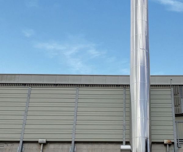
- External finish formed by 1 m long elements in Aisi 304 (1.4301)
- FBA finish (glossy) or copper or other materials
- Angles of insertion horizontal pipe from 90º to 135º
EXTERNAL SUPPORTING DUCT – System suitable for high temperature fumes
Freestanding chimney built from a resistant external metal conduit with circular section not in contact with fumes. Inside it contains the flue, insulated with high density rock wool 100 kg / m3 thicknesses: 30, 40, 50, 60, 80 and 100 mm (depending on the temperature of the fumes), factory mounted, supported and guided from elements with a low thermal bridge.
THE INTERNAL FLUE is made of S235 JRW corten steel or AISI 304 (1.4301) stainless steel AISI 316 (1.4401 or 1.4404) stainless steel or as an option it is possible to use any product from our range of modular chimney in JR S235 steel (or higher) S235 JRW corten steel (or higher). The external finish is performed by sandblasting the entire external surface with neutral sand, two coats of epoxy primer and finishing coat as from RALcolor chart.
Final thickness from 100 to150 micron.
CONCENTRIC FREESTANDING
Built as a multiple flue equipped with concentric flues inside the self-supporting external flue. The flue with the largest diameter is insulated along its entire length with high density rock wool 100 kg/m3 thickness 30, 40, 50, 60, 80 and 100 mm (depending on the temperature of the fumes).
Internal ducts made of S235 JRW corten steel (or higher), Aisi 304 (1.4301) stainless steel Aisi 316 (1.4401 or 1.4404) stainless steel, while for the external bearing duct the materials used are: JR S235 steel (or higher), S235 JRW steel corten (or higher), Aisi 304 (1.4301) stainless steel, Aisi 316 (1.4401 or 1.4404) stainless steel.
Two exterior finishing options
- Sandblasting up to grade 2.5 s / sis-055900 of the entire external surface with neutral sand; two coats of epoxy primer and final finish as per RAL color chart. Final thickness from 100 to 150 microns.
- Outer jacket made up of 1 m long elements with continuous junction made of Aisi 304 (1.4301) stainless steel or AISI 316 (1.4404) stainless steel.
Fixing elements
FIXING WITH AN ANCHOR CAGE
FIXING WITH AN ANCHOR CAGE
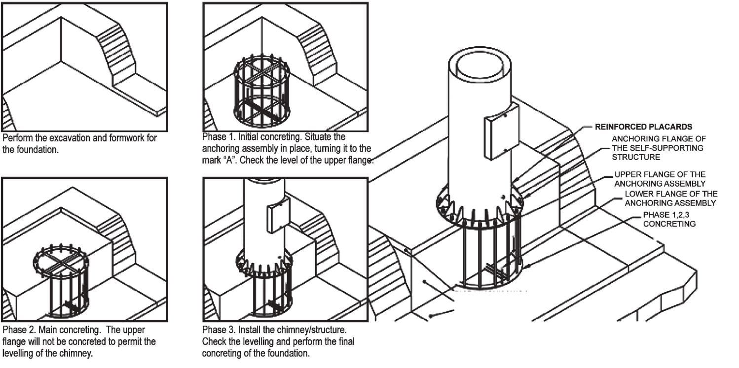
This fixing system consists of an anchor cage template supplied by the manufacturer, sized and consisting of two flanges spaced by screws, which also allow the correct leveling of the assembly. The anchor cage template is embedded in the concrete during the execution of the foundation following the procedures communicated by the manufacturer.
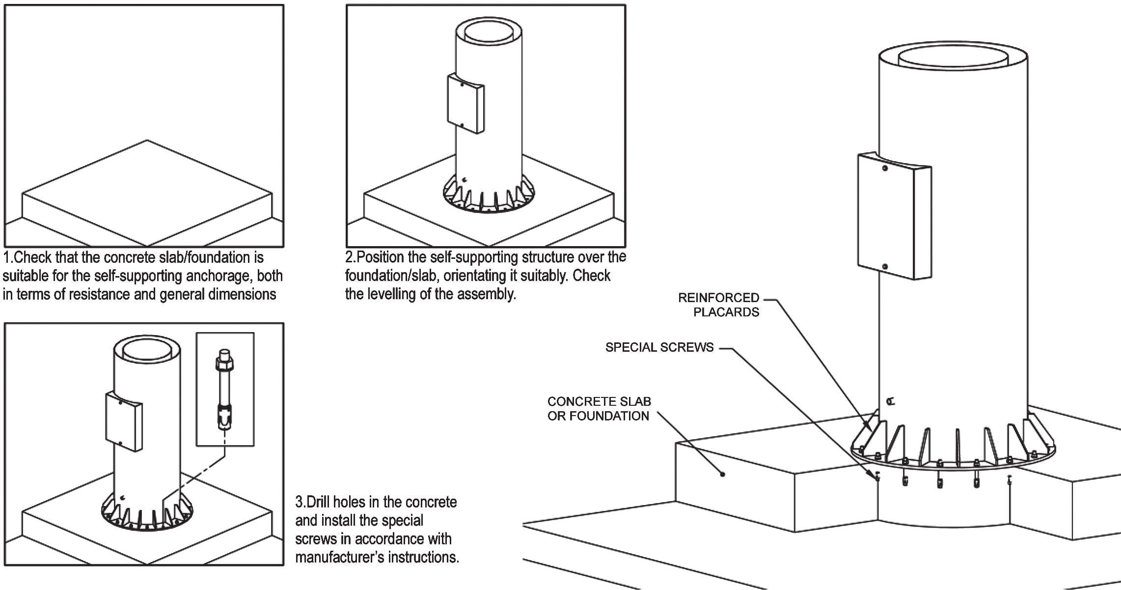
FIXING ON EXISTING FOUNDATION
The freestanding chimney will be fixed on the base by means of specific screws depending on the base foundation and the resulting forces, tightened directly on the base flange of the chimney. It is important to proceed as follows:
- Check that the concrete foundation is suitable for anchoring the freestanding chimney, both in terms of mechanical strength and overall dimensions.
- Position the freestanding chimney over the foundation, orienting it appropriately. Check assembly leveling.
- Drill holes in concrete and install special screws according to manufacturer’s instructions.
FREESTANDING CHIMNEYS
Accessories
INTERMEDIATE SUPPORTS AND FIXING ELEMENTS
The use of intermediate supports in the systems allows to optimize the resistant sections of the chimney or structure and allows the simplification of civil works. Therefore, they should always be used whenever possible. The different types of supports are classified as follows and furthermore the supports can be used individually or in combination:
- Roof supports, where the freestanding chimney or structure is stabilized thanks to the use of a support anchored to a suitably resistant roof.
- Wall supports, in this case, one or more intermediate levels of the structure or of the freestanding chimney are fixed in place by means of lateral anchors to a resistant wall. 84
PLATFORMS
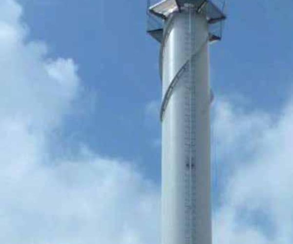
The platforms are used to facilitate access to the measuring and sampling points of the chimney or structure and to facilitate the maintenance of elements such as lightning rods or signal lights. The materials that are normally used for the construction of our platforms are:
- Floor in Aisi 304 (14301) stainless steel with non-slip finish.
- Handrail in tubular sections of stainless steel Aisi 304 (14301)
- Structure in Aisi 304 (1.4301) or S235 stainless steel profiles in painted laminated carbon steel.
The angle of the platform coverage can vary according to your needs (normally it is between 150º and 360º).
STAIRS
The stairs allow easy access to the platforms and normally start at the reference level of the installation. The maximum distance between the starting level and the upper finishing level must not exceed 9 m, as per current legislation. For distances greater than 9 m it is necessary to use an intermediate rest and can be obtained through two different configurations:
- Intermediate platforms with similar characteristics to the main platforms, as described above, but smaller in size.
- Relocation of the stair axis, where the stair is repositioned towards another element, thus creating an intermediate level of safety.
LIGHTNING CONDUCTORS
According to the terms established by the European standard UNE-EN 13084-1, freestanding chimney can be considered metal structures with continuous electrical conductivity. For this reason do not need specific protection against lightning or electric shocks. However, the chimney may include a lightning rod in order to protect nearby buildings or equipment from receiving electric shocks. The system normally used consists of a Franklin point installed on a stainless steel pole.
VISIBILITY
The characteristics of the report must be defined in the project report, and based on the geographical coordinates of the plant, generally the configuration used for the report is composed of the following elements:
- Night beacons with red lights, 16 cd each, long lasting (> 100,000 h), low consumption thanks to the use of LEDs.
- Daytime signaling with alternating red and white colored bands in the upper part of the chimney (normally between 1/3 and 1/2 of the total height).


